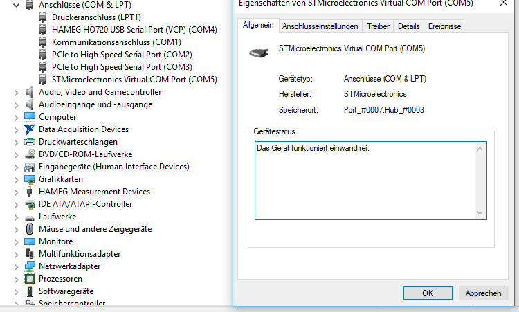
Unable to open serial port, another device might be using COM1. Run chgport /query. If the built-in Windows serial driver on the VDA is auto-assigning DeviceSerial0 to a COM1 port of your VDA, do the following: A. Open CMD on the VDA and type NET USE. Delete any existing mapping (for example, COM1) on the VDA. NET USE COM1 /DELETE. Download Multifunction Device for Windows to modem driver. Download Multifunction Device for Windows to modem driver. Join or Sign In. Sign in to add and modify your software. LCD Segment Drivers Multi-function LCD Segment Drivers BU91510KV-M MAX 216 Segment(54SEG x 4COM) General Description The BU91510KV-M is 1/4 or 1/3 Duty General-purpose LCD driver that can be used for frequency display in electronic tuners under the control of a microcontroller. The BU91510KV-M can drive up to 216 LCD Segments. Lost both COM1 & COM2 ports during terminal session with a managed switch. Device Manager gives status as: 'Windows cannot load the device driver for this hardware. The driver may be corrupted or missing. (Code 39)' on both ports. Drivers - serial.sys and serenum.sys (file ver 5.2.3790.3959: 64KB/18KB: 2/17/2007) 3:58AM.
UART stands for 'Universal Asynchronous Receiver Transmitter.' For our purposes, it is a relatively simple device that illustrates the the nature of device controllers (DCs) in general.
A UART acts as the interface between an I/O bus and a serial device, such as a mouse or modem, which communicate with a computer one bit at a time. On a PC, there are two UARTs that connect to the COM1 and COM2 ports on the back of the computer.

Com1 Multifunction Devices Driver Win 7

Com1 Multifunction Devices Driver Scanner
Com1 Multifunction Devices Driver Win 7
Com1 Multifunction Devices Driver Scanner
The job of a UART is to accept bytes of data from the CPU 8 bits at a time (in parallel) and to transmit them one bit at a time (serially) to whatever device is plugged into its connector on the back of the computer. At the same time, it receives data bits serially from the device, which it assembles into bytes that the CPU reads in parallel.
Internally, a UART has several different registers that the CPU can read and write. The following table lists just a few of them. The left column lists the addresses the CPU uses to access these registers for a UART being used for COM1 in a standard PC.
| Address | Name | Function |
|---|---|---|
| 0x3F8 | RBR | Read Buffer Register. The CPU reads data bytes from this register. |
| 0x3F8 | THR | Transmitter Holding Register. The CPU writes data bytes to this register. |
| 0x3F9 | IER | Interrupt Enable Register. The CPU writes a byte to this register to tell the UART when to generate interrupts. Individual bits within the byte indicate whether to generate an interrupt when the RBR is full, when the THR is empty, or when an error condition is detected. |
| 0x3FA | IIR | Interrupt Identification Register. The CPU reads this register to find out why the UART generated an interrupt. |
| 0x3FB | LCR | Line Configuration Register. The CPU writes bytes to this register to configure parameters like baud rate (the speed at which bits are sent and received) and parity (error checking) options. |
| 0x3FD | LSR | Line Status Register. The CPU reads from this register to find out whether the RBR is full, whether the THR is empty, or whether an error condition has been detected. |
This table is far from complete, but it is accurate as far as it goes. The registers described here give us enough to work with so we can see how a Device Controller works.
Com1 Multifunction Devices Driver Touchpad
To understand how a UART operates we also need to introduce two additional registers that are not in the table, and which the CPU cannot access directly. These are the shift registers connected to the Rx and Tx wires. The Rx shift register (Rx SR) is an 8 bit register that receives incoming serial data. When 8 data bits have arrived, the Rx SR is transferred in parallel into the 8-bit RBR. While waiting for the CPU to read from the RBR, the Rx SR can start receiving bits from the next input byte on the Rx line. Likewise, there is a Tx shift register (Tx SR) that gets loaded from the THR in parallel, and then shifts the bits out over the Tx wire one at a time. While the Tx SR is transmitting a byte, the CPU can write another data byte to the THR.
